Malaysia airlines plane may have crashed 239 people on board #12

Status
Not open for further replies.
I just hope this new lead finding is not another false lead for the families.

However it will be sad to know everyone would most likely be deceased and I am sure that is just as aweful for the families as if the plane was still missing.

I feel so badly for the families.
 
Keir Simmons ‏@KeirSimmons 1m https://twitter.com/KeirSimmons

Relatives of flight 370 passengers leave a 2 hour meeting in Kuala Lumpur... Have been told officials expect news within a few days they say
 
Earlier, the crew of the Poseidon told ABC News that their aircraft was getting radar hits of "significant size" in water's beneath the surface near the objects but that it was too early to tell if these hits were related to debris from the missing plane.

"This is a lead, this is probably the best lead we have right now, but we have to find them, see them, assess them," Young said of the objects.

"If there is a positive ID (of the debris) ... then (investigators) will likely study and model currents and flows in the ocean as soon as possible to find out where to look for the black boxes. Or, rather, listen for them, as they will likely still be sending out sonar signals at this point (about 30 days after an aircraft goes down)," Sidney Dekker, an expert on aviation safety, told USA TODAY in e-mailed comments.

http://www.nwcn.com/news/washington/possible-malaysia-plane-debris-251191591.html
 
Perhaps this has been posted, but does anyone have an ocean currents map?

No, but upthread this Australian article was posted:

Ocean expert Robin Beaman said debris could have been carried hundreds of kilometres since the satellite images were captured on March 16.
“The currents are drifting at one or two nautical miles per hour so it certainly makes sense that it could have drifted several hundred miles by now,” he said...The wind is moving in an easterly direction which means anything floating on the surface will also drift in that direction but at some point it just becomes waterlogged and sinks.”

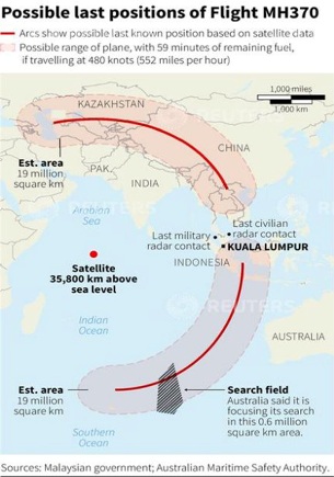
If the plane entered the water on March 8 at or near its (ETA: western) fuel limit on the southern arc satellite-ping "red line", a steady east-ward drift of wreckage would lead right into the Australian search area. It's not conclusive, but suggestive:

Bg6Qm99.jpg
 
Australian officials say the search for possible objects has ended for today.
by roddymansfield 9:06 AM

http://news.sky.com/story/1228912/missing-plane-live-updates-search-for-debris

Earlier, the crew of the Poseidon told ABC News that their aircraft was getting radar hits of "significant size" in water's beneath the surface near the objects but that it was too early to tell if these hits were related to debris from the missing plane.

"This is a lead, this is probably the best lead we have right now, but we have to find them, see them, assess them," Young said of the objects.

"If there is a positive ID (of the debris) ... then (investigators) will likely study and model currents and flows in the ocean as soon as possible to find out where to look for the black boxes. Or, rather, listen for them, as they will likely still be sending out sonar signals at this point (about 30 days after an aircraft goes down)," Sidney Dekker, an expert on aviation safety, told USA TODAY in e-mailed comments.

http://www.nwcn.com/news/washington/possible-malaysia-plane-debris-251191591.html

Image from article

Boeing Anti-Submarine Plane Joins Missing Jet Search

[URL=http://s1220.photobucket.com/user/kimi_SFC/media/subjoinssearch_zps3e724e44.jpg.html][/URL]
 
I really hope this is the plane. The families have been through so much in these last couple weeks and it would be nice if they could get some closure.

Sure, they'll probably never know (nor will we) what really happened the day the plane disappeared, but at least having bits and pieces of the plane found will be something.

If this debris did float from the original crash site, I really hope that search and rescue teams will be able to find it.
 
Yes. if you click on "helping out" under "crowdsurfing campaign", it takes you to Tomnod.

https://www.digitalglobe.com/

Here is a decent short article DigitalGlobe Powers Crowdsourced Hunt For Missing Malaysian Flight 370

DigitalGlobe used its satellites to capture some 3,200 square km of the area where the flight could have gone down....

...it shows the same images to many different people, and if enough people tag the same little square on the grid, an expert will review that area to see if the item of interest is worth investigating.

....the tedious legwork is done by what amounts to throngs of worker bees, thus freeing up the time and resources of the experts to do more sophisticated work.

Tomnod FB
 
Hi all, I was up all night and watching CNN.. I know nothing about planes, ships, even canoes so please dont think I am nuts. If they find these are parts of the plane can they send a submarine down there? It would be a blessing as they could really ID. it. My thoughts and prayers are with the families. I cant put the picture of the mom out of my mind.
 
Nope, the pilot on CNN said it was possible even if the plane were flying on autopilot and ran out of gas.

I was just passing along what he said. I'm not saying it would have been a smooth landing but it doesn't just drop out of the sky like someone (and myself) wondered previously in the thread.

That is very interesting. I see a CNN article where a pilot, Robert Goyer, talks about if the plane ran out of fuel, the auto pilot may have remained on and that the "dynamics such a crash scenario are complex." Without the engines or APU, there is no electricity to power the autopilot nor the control surfaces. Now, planes can deploy a ram-jet to provide minimal power to control things in such a case, so maybe the plane would do that on its own. I don't know. There is the case of AirTrans Airbus that ran out of fuel over the Atlantic and its pilots had to glide to an airport. Could a 777 autopilot attempt a water landing on its own without the engines and without pilot assistance? I have no idea.

http://www.cnn.com/2014/03/20/opinion/goyer-malaysia-flight-objects/index.html?hpt=hp_c2
 
http://cnews.canoe.ca/CNEWS/World/2014/03/19/21545156.html
bbm
"If the debris is from the plane, investigators would face a daunting task to retrieve the "black box" data and voice recorders needed to help understand what caused the disaster.

University of Western Australia Professor of Oceanography Charitha Pattiaratchi said that, based on currents in the area, if the debris is from the plane it probably would have entered the water around 300-400 km to the west.

The search area covered an ocean ridge known as Naturalist Plateau, a large sea shelf about 3,500 metres (9,800 feet) deep, Pattiaratchi said. The plateau is about 250 km (150 miles) wide by 400 km (250 miles) long, and the area around it is close to 5,000 metres (16,400 feet) deep.

"Whichever way you go, it's deep," Pattiaratchi said."
 
Here is a decent short article DigitalGlobe Powers Crowdsourced Hunt For Missing Malaysian Flight 370

DigitalGlobe used its satellites to capture some 3,200 square km of the area where the flight could have gone down....

...it shows the same images to many different people, and if enough people tag the same little square on the grid, an expert will review that area to see if the item of interest is worth investigating.

....the tedious legwork is done by what amounts to throngs of worker bees, thus freeing up the time and resources of the experts to do more sophisticated work.

Tomnod FB

This is not a new concept. From 2000/2001 NASA has had a few experimental projects, mainly identifying craters on Mars with images from orbiters. IIRC it was called ClickWorkers.
 
WHat I don't get is why if they were headed to Lankowi, the reciprocal approach that he was planning to use (from over the water) was not already pre-programmed into the FMC as a "common, default or emergency alternate airfield". I am totally speaking from personal thought/opinion on this, but I would put money on it that every single aircraft in the Malaysian Airlines fleet bigger than a hang glider would have Lankowi as a preset for anything from an easy shortcut for crews entering flight data on pre-flight through to the above mentioned reasons... and I will tell you something else scary for those who live in aviation oblivious bliss... that airliner could have flown itself back to lankowi, put itself into the approach (providing lankowi has an ILS of course) and come to a complete wheels stop landing after touching down on the "Keys" at the end of the runway with a a rate of accuracy better than most humans can achieve...

...even if everyone on board had died just moments after the turnaround to track for LKW ...

Whoa, whoa, whoa. Do I understand that correctly - that the plane on auto-pilot could have landed itself? I mean, landed itself at the airport if they had put in the destination as the airport?
 
http://www.chicagotribune.com/news/chi-missing-malaysia-plane-20140320,0,1370580.story

"The owner of a Norwegian car carrier said it planned to search through the night for two large objects sighted off Australia that could be debris from a missing Malaysian jetliner, despite the official search being suspended because it was too dark.

The Hoegh St. Petersburg was the first ship to arrive in the area where the two objects were spotted by satellite four days ago in one of the remotest parts of the globe, around 1,500 miles southwest of Perth, or about the distance from New York City to Dallas.

"We will continue searching during the night at reduced speed and with all spotlights available, and we will increase the speed again when the light comes back," Ingar Skiaker, Chief Executive of Hoegh Autoliners, told a news conference in Oslo.

"We have not had any report of any finds, but if or when they find something... the captain will report to the Australian authorities first," he said".
 
This is Air France - done by the French equiv of NTSB. THey model NTSB, however they are much more reluctant to release the actual transcript of CVR! It over 200 page so 10% is not problem.

Did it this way because it takes some to load the whole report!

Table of Contents
SAFETY INVESTIGATIONS 1
TABLE OF ILLUSTRATIONS 7
GLOSSARY 11
SYNOPSIS 17
ORGANISATION OF THE INVESTIGATION 19
1 - FACTUAL INFORMATION 21
1.1 History of Flight 21
1.2 Killed and Injured 24
1.3 Damage to Aircraft 24
1.4 Other Damage 24
1.5 Personnel Information 24
1.5.1 Flight crew 24
1.5.2 Cabin crew 29
1.6 Aircraft Information 30
1.6.1 Airframe 30
1.6.2 Engines 30
1.6.3 Weight and balance 30
1.6.4 Condition of the aircraft before departure 31
1.6.5 Maintenance operations follow-up 31
1.6.6 Information on the airspeed measuring system 31
1.6.7 Checks and maintenance of the Pitot probes 33
1.6.8 Radio communications system 34
1.6.9 Systems function 35
1.6.10 Specific points on overspeed 42
1.6.11 Angle of attack protection and stall warning 43
1.6.12 REC MAX and OPTI flight levels 45
1.6.13 Onboard weather radar 45
1.7 Meteorological Conditions 46
1.7.1 Meteorological situation 46
1.7.2 Forecast charts 46
1.7.3 Meteorological analyses 47
1.8 Aids to Navigation 48
1.9 Telecommunications 48
1.9.1 Communications between the aeroplane and the ATC centres 48
1.9.2 Means of monitoring used by air traffic control services 49
1.9.3 Coordination between the control centres 52
1.10 Aerodrome Information 53
1.11 Flight Recorders 53
1.11.1 Flight recorder opening operations and read-out 54
1.11.2 Analysis of the flight recorder data 57
1.11.3 Analysis of computers 62F-
1.12 Wreckage and Impact Information 64
1.12.1 Localisation of the floating debris and the wreckage site 64
1.12.2 Work performed on floating debris 66
1.12.3 Examination of the wreckage 77
1.12.4 Summary 81
1.13 Medical and Pathological Information 81
1.14 Fire 81
1.15 Survival Aspects and SAR 81
1.16 Tests and Research 83
1.16.1 Underwater search and recovery operations 83
1.16.2 Study of unreliable indicated airspeed events
(temporary loss or anomalies) occurring in cruise on Airbus A330/A340 85
1.16.3 Analysis of functioning of systems 88
1.16.4 Analysis of aircraft performance 90
1.16.5 Reconstruction of the information available to the crew 93
1.16.6 Simulation of flight AF 447 in the Eurocat system 99
1.16.7 Aspects relating to fatigue 100
1.16.8 Work on Human Factors 101
1.16.9 Examination of the cockpit seats
106
1.17 Information on Organisations and Management 110
1.17.1 Organisation of Air France 110
1.17.2 Organisation of oversight of the operator by the DGAC 126
1.17.3 Air traffic services for a trans-oceanic flight 129
1.17.4 Search and Rescue (SAR) 130
1.18 Additional Information 136
1.18.1 Type Certification and continuing airworthiness 136
1.18.2 Information supplied to flight crews on the unreliable IAS situation 147
1.18.3 Information on the Stall 150
1.18.4 Simulator fidelity 154
1.18.5 Testimony 157
1.18.6 Previous Accidents and Recommendations 159
1.19 Useful or Effective Investigation Techniques 162
1.19.1 Resources used for phase 4 162
1.19.2 Resources used for phase 5 166
2 - ANALYSIS 167
2.1 Accident Scenario 167
2.1.1 From the beginning of the CVR recording until
the autopilot disconnection 167
2.1.2 From the autopilot disconnection to triggering of the STALL 2 warning 171
2.1.3 From the triggering of the STALL 2 warning until the end of the flight 178
2.2 Pilot Training and Recurrent Training 182
2.2.1 Manual aeroplane handling and functional representation of flight 183
2.2.2 CRM training and exercises 184
2.2.3 Augmented crews 184
2.2.4 Flight simulators 185
2.2.5 Aeroplane behaviour in reconfiguration laws 186
2.3 Ergonomics 187
2.3.1 ECAM 187
2.3.2 Operation of the flight directors 188
2.3.3 Stall warning (operation and identification) 189
2.4 Operational and technical feedback 190
2.5 Oversight of the Operator by the national aviation safety
authority (DGAC/DSAC) 192
2.6 SAR operations 193
2.7 Radio-communications with control services 194
2.7.1 Controllers’ and crew’s planned actions 194
2.7.2 Limits on the use of the Eurocat system in Senegal 194
2.7.3 Alert service provision 195
2.8 Lessons learnt from the search for the wreckage of flight AF 447 195
3 - CONCLUSION 197
3.1 Findings 197
3.2 Causes of the Accident 199
4 - SAFETY RECOMMENDATIONS 203
4.1 Recommendations from Interim Report n°2 203
4.1.1 Flight Recorders 203
4.1.2 Certification 204
4.2 Recommendations from Interim Report n°3 204
4.2.1 Recommendations on Operations 204
4.2.2 Recommendation relating to Certification 205
4.2.3 Recommendations relating to Flight Recorders 205
4.2.4 Recommendations relating to Transmission of Flight Data 206
4.3 New Recommendations 207
4.3.1 SAR coordination plans over maritime and remote areas 207
4.3.2 Training of SAR operators 207
4.3.3 Organisation of SAR in France 208
4.3.4 Air Traffic Control 208
4.3.5 Initial and recurrent training of pilots 208
4.3.6 Improving flight simulators and exercises 210
4.3.7 Ergonomics 210
4.3.8 Operational and Technical Feedback 212
4.3.9 Oversight of the Operator 212
4.3.10 Release of Drift Measuring Buoys 213
5 - CHANGES MADE FOLLOWING THE ACCIDENT 215
5.1 Air France 215
5.1.1 Aeroplane maintenance and equipment 215
5.1.2 Modifications to reference systems 215
5.1.3 Crew training 215
5.2 Airbus 216
5.3 EASA 216
5.3.1 Certification measures to improve aviation safety 216
5.3.2 Rulemaking actions from EASA to improve aviation safety 216
5.4 Aviation industry actions 217
Table of Illustrations
Figure 1: Flight profile 23
Figure 2: Position of the Pitot probes on the Airbus A330 32
Figure 3: Pitot probe (with protection caps) 32
Figure 4: Diagram of the speed measurement system architecture 33
Figure 5: FCU display 37
Figure 6: PFD in normal law 39
Figure 7: PFD in alternate 2 law 39
Figure 8: Pitot probe diagram 40
Figure 9: Overview 41
Figure 10: Effect of a drop in total measured pressure on standard altitude
and vertical speed 42
Figure 11: Evolution of stall warning threshold in relation to Mach 44
Figure 12: Example of a “PROG” page from FMS 45
Figure 13: TEMSI chart overlaid with infrarouge image at 0 h 00 47
Figure 14: Strip filled out by ATLANTICO controller 49
Figure 15: Representation of air traffic by the Eurocat system 51
Figure 16: FDR 54
Figure 17: CVR 54
Figure 18: FDR CSMU after removal of cover 54
Figure 19: FDR memory board 55
Figure 20: Removal of internal protective layers 55
Figure 21: Opening of CVR CSMU 56
Figure 22: CVR memory board after removal of thermal protections 56
Figure 23: CVR memory boards before cleaning 56
Figure 24: Level of turbulence observed during flight 58
Figure 25: Position and detail of “AIR DATA” selector 59
Figure 26: Parameters from 2 h 10 min 04 to 2 h 10 min 26 60
Figure 27: Parameters from 2 h 10 min 26 to 2 h 10 min 50 61
Figure 28: Parameters from 2 h 10 min 50 to 2 h 11 min 46 62
Figure 29: Optical disk showing the location of the readable zones 63
Figure 30: Memory component from one of the FCDC 64
Figure 31: All of floating debris (found between 6 and 26 June), last known position
and wreckage site 65
Figure 32: Wreckage localisation 66
Figure 33: Position of the recovered parts (exterior and cargo) 66
Figure 34: Position of the cabin part debris recovered in relation to the aircraft layout 67
Figure 35: Part of Galley G3: downwards deformation at the level of the galley’s heavy parts 68
Figure 36: Luggage rack fitting deformed towards the front Toilet door (L54) 68
Figure 37: Metallic stiffeners deformed by buckling 68
Figure 38: Floor of the LDMCR: with bottom-upwards deformation 69
Figure 39: Ceiling of the LDMCR: with top-downwards deformation 69
Figure 40: Passenger oxygen container recovered closed: the deformations
on the cover matched those on the box 69
Figure 41: Passenger oxygen container recovered open: the three pins are in place 70
Figure 42: Flap extension mechanism (or flap track) No. 3 in retracted position 70
Figure 43: Part of the No. 3 flap track fairing on the left wing 71
Figure 44: Fin – In the foreground the base of the fin with the central and forward
attachment lugs 71
Figure 45: Rib 2 bent upwards as a result of bottom-upwards compression loads 72
Figure 46: HF antenna support 72
Figure 47: Arm 36G, right view: failure of the rudder attachments 73
Figure 48: Frame 87: shearing of the frame and fuselage skin along the frame 74
Figure 49: Right-hand aft lug: shearing of the fuselage along main frames 86-87 74
Figure 50: Frames 84 to 87: S-shaped deformation of frame 87, with frames 84 and 85
pushed in backwards; failure of the horizontal stabiliser actuator supports
between frames 86 and 87 (red circle) 75
Figure 51: Fin centre and aft attachments 75
Figure 52: Rear view of the left-hand aft lug: there were marks showing a backwards
pivoting of frames 86 and 87 76
Figure 53: Tensile failure of the centre spar at the level of the attachment
of the lateral load pick-up rods 76
Figure 54: Compression failure of the aft spar at the level of the attachments
of the lateral load pick-up rods and failure of the left-hand rod by buckling 77
Figure 55: Sonar Images of the debris field 77
Figure 56: Parts of the fuselage 78
Figure 57: Left engine air intake 78
Figure 58: Engine pylon 79
Figure 59: Cartography of the parts subsequently brought to the surface 79
Figure 60: Front view of engine 80
Figure 61: Trimmable horizontal stabiliser screwjack after being raised on board 80
Figure 62: Evolutions of recorded angles of attack and of the stall warning trigger threshold 89
Figure 63: Comparison between the recorded positions of the elevator and THS
and the simulation 90
Figure 64: Comparison between altitudes of the aeroplane and the simulation (longitudinal axis) 91
Figure 65: Flight envelope 92
Figure 66: Evolution of normal acceleration recorded at the time of activation
of the stall warning 92
Figure 67: Speed displays on the PFD 93
Figure 68: Evolution of the 3 CAS 94
Figure 69: Evolution of FD crossbars 96
Figure 70: Position of the area where ECAM messages are displayed 97
Figure 71: ECAM displays at different moments (if no message has been erased) 97
Figure 72: Evolution of the REC MAX (simulation) Source Airbus 99
Figure 73: Source: Airbus FCOM supplied to Air France 103
Figure 74: Source FCOM Airbus 104
Figure 75: Source TU Air France 104
Figure 76: View of the cockpit seats 106
Figure 77: General view of the left seat 106
Figure 78: The seat’s horizontal position adjustment systems 107
Figure 79: Right seat armrest on the side-stick side 108
Figure 80: Roller marks on the guidance rail 108
Figure 81: Right side seat cushion 109
Figure 82: Marks on the adjustment mechanism 109
Figure 83: Dial indicating armrest position 110
Figure 84: Malformation of the crotch belt fastening 110
Figure 85: A typical display on a flight logging interface 111
Figure 86: Strip created after coordination between ATLANTICO and DAKAR Océanic 129
Figure 87: Arrangement of the SRR in metropolitan France 133
Figure 88: Lift graph with high and low Mach 150
Figure 89: Flight envelope at high altitude 151
Figure 90: Alucia 163
Figure 91: AUV REMUS 6000 163
Figure 92: General view using sonar imaging: 120 kHz, range of 700 m 163
Figure 93: Engine 164
Figure 94: Wing 164
Figure 95: Section of fuselage 164
Figure 96: Landing gear 165
Figure 97: Overlay of sonar images taken with various settings: 120 kHz,
700 m range scale - 410 kHz, 100 m range scale - 410 kHz, 50 m range scale 165
Figure 98: Visualisation of the photo mosaic obtained with REMUS AUV images
and the aeroplane debris identifie
d by using the REMORA ROV 166


http://www.bea.aero/docspa/2009/f-cp090601.en/pdf/f-cp090601.en.pdf
 
Status
Not open for further replies.

Staff online

Members online

Online statistics

Members online
113
Guests online
3,954
Total visitors
4,067

Forum statistics

Threads
592,117
Messages
17,963,513
Members
228,687
Latest member
Pabo1998
Back
Top